
Sentaurus Topography 3D
2. Example: Material Deposition
2.1 Overview
2.2 Generating the Initial Structure
2.3 Performing Material Deposition
2.4 Saving the Final Structure
2.5 Integration With Sentaurus Process
Objectives
- To perform a deposition simulation using Sentaurus Topography 3D.
- To use Sentaurus Topography 3D functionality from within Sentaurus Process.
2.1 Overview
This section introduces the most common features of Sentaurus Topography 3D in the context of a simple example of high-density plasma (HDP) deposition.
The complete project can be investigated from within Sentaurus Workbench in the directory Applications_Library/GettingStarted/sptopo3d/depo_hdp. If you are not familiar with Sentaurus Workbench projects, the preprocessed script file depo_hdp_t3d.cmd can be found in this directory.
To download the preprocessed script file, right-click the following link and choose Save Target As: depo_hdp_t3d.cmd.
To execute the file in Sentaurus Topography 3D on the command line, type:
> sptopo3d depo_hdp_t3d.cmd
After the command file is executed, the generated TDR file is final.tdr.
2.2 Generating the Initial Structure
This section shows how to use geometric etching and deposition steps to generate a simple trench to be used as the initial structure in Sentaurus Topography 3D. In this example, due to the symmetry of the problem, only one-quarter of the structure needs to be simulated. Sentaurus Topography 3D exploits such symmetries by using reflective boundary conditions, which are applied by default. This allows you to save considerable computation time.
The initial structure is defined with the define_structure command:
define_structure material=Silicon point_min={0 0 0} point_max={0.1 0.1 0.3}
This command creates a silicon cuboid, which becomes the basis for further etching or deposition processes (units are μm).
The input structure to be processed in Sentaurus Topography 3D also can
be loaded from a TDR boundary file, for example:
define_structure file=input.tdr
A cuboid shape is defined that is used to etch a trench from the initial structure with the command:
define_shape type=cube name=trench point_min={0.05 0.05 0.1} \
	point_max={0.1 0.1 0.3}
Geometric etching is performed using the shape defined above:
etch shape=trench
Finally, the initial structure is saved before proceeding to the next steps using the save command:
save file=n@node@_init.tdr
In order for the saved file to be available in Sentaurus Workbench for visualization, the file name contains the running-node parameter @node@.
If the file name is not specified, the initial structure will be appended to the TDR file saved at the end of the simulation, after processing is performed.
Figure 1 shows the initial structure.
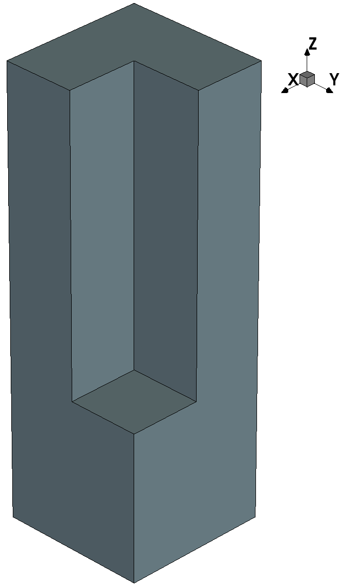
Figure 1. Generated initial structure. (Click image for full-size view.)
To activate the 2D mode of Sentaurus Topography 3D, the initial structure must be two dimensional. In this example, the parameters point_min and point_max in the define_structure and define_shape commands would contain only two coordinate values. All the subsequent commands are exactly the same as in three dimensions.
2.3 Performing Material Deposition
The next subsections demonstrate the use of the deposition models in Sentaurus Topography 3D. This example illustrates the high-density plasma (HDP) deposition model.
Other deposition models, such as electroplating deposition, low-pressure chemical vapor deposition, physical vapor deposition, and plasma-enhanced chemical vapor deposition, can be specified similarly (see the Sentaurus™ Topography 3D User Guide).
2.3.1 Defining the Deposition Model
You use the define_deposit_machine command to specify the deposition model to be used and the values of its parameters.
A deposition machine that uses the HDP deposition model is defined with the command:
define_deposit_machine model=hdp material=Oxide rate=2 \
	anisotropy=0.7 exponent=100 redeposition=0.1 \
	sputter_rate=0.95 s1=5.5 s2=-6 sticking=0.1
In this example, the define_deposit_machine command specifies the deposited material, the rate, the anisotropy, the angular distribution exponent, the redeposition coefficient, the sputter rate, the sputtering coefficients, and the sticking coefficient.
All parameters of deposition models are specified with the define_deposit_machine command and are material independent. This is in contrast to the etching models, where different parameter values can be assigned to different materials.
The HDP deposition model assumes that a neutral flux and an ion flux reach the surface. The anisotropy factor, given by the anisotropy parameter, is 0.7. It is related to the weight of the ion flux on the deposition rate with respect to the neutral flux.
The incoming neutral particles can either stick to the surface and be deposited, or can be re-emitted. In this example, the sticking probability is set to 0.1 with the parameter sticking. The deposition rate of neutrals on a flat unshadowed surface is proportional to the parameter rate (here, set to 2 μm/s).
The incoming ion flux is characterized by an angular source distribution. In this example, the source distribution is modeled as cosm(θ). Here, θ denotes the angle between the incoming direction and the vertical direction, and m is an integer that determines the directivity of the ion beam. In this example, it is set to 100 with the parameter exponent.
Incoming ions are deposited and, at the same time, can induce a flux of sputtered particles. The amount of sputtered material is highly dependent on the angle between the incoming direction of the ions and the normal to the target surface. The dependency of the amount of sputtered material on such an angle is specified by the yield function. In the HDP deposition model, the yield function is defined by the values of the parameters s1 and s2, which are 5.5 and –6, respectively. For details about the yield function, see the Sentaurus™ Topography 3D User Guide.
The amount of sputtered material that redeposits is set by the redeposition parameter (0.1 in the example). The sputter_rate parameter (0.95 μm/s in the example) specifies a scaling value for the net amount of the redeposited flux, which determines how much redeposition contributes to the oxide growth.
The total amount of deposited oxide is the amount of deposited neutrals and ions, plus the amount of sputtered material that redeposits, minus the amount of locally sputtered material.
For details about the physics of the HDP deposition model and other deposition models, see the Sentaurus™ Topography 3D User Guide.
2.3.2 Starting the Deposition Process
To start the simulation of a deposition process on the structure lasting 0.04 minutes, using the machine defined in Section 2.3.1 Defining the Deposition Model, use the command:
deposit spacing={0.01 0.01 0.015} time=0.04
The spacing parameter specifies the uniform grid used by the level-set algorithm to evolve the surface. Here, dx=0.01 μm, dy=0.01 μm, and dz=0.015 μm.
Sentaurus Topography 3D prints information about the progress of the deposition process in the log file:
deposit
 time = 0.04 min.
 material = 'Oxide'.
 Serial computation mode.
 Boundary conditions:
 reflective at x min, reflective at x max,
 reflective at y min, reflective at y max.
 --------------
 Remeshing... took 0.1 s.
 [  1]:   t= 0.00 Progress: [>         ] 11%  Remaining:   280.1s.
 [  2]:   t= 0.01 Progress: [=>        ] 23%  Remaining:   234.6s.
 [  3]:   t= 0.01 Progress: [==>       ] 35%  Remaining:   192.2s.
 [  4]:   t= 0.02 Progress: [===>      ] 47%  Remaining:   165.1s.
 [  5]:   t= 0.02 Progress: [====>     ] 59%  Remaining:   131.5s.
 [  6]:   t= 0.03 Progress: [======>   ] 71%  Remaining:    98.2s.
 [  7]:   t= 0.03 Progress: [=======>  ] 83%  Remaining:    57.2s.
 [  8]:   t= 0.04 Progress: [========> ] 95%  Remaining:    16.1s.
 [  9]:   t= 0.04 Progress: [==========]100%  Remaining:     0.0s.
 --------------
 Grid to brep conversion... Performing boolean operations:
  simplify: 0% : 100%

deposit done.
Decreasing the size of the spatial discretization increases the required memory and the CPU time because there are more grid points to store and process. Usually when setting up a deposition or an etching simulation, you need to find a compromise between the required accuracy and the available computational resources. A good understanding of the relationship between the discretization sizes and the resulting accuracy is important not only when setting up a simulation, but also when interpreting its results.
2.4 Saving the Final Structure
To save the final structure, use the save command:
save file=n@node@_final.tdr
When Sentaurus Topography 3D is run from within Sentaurus Workbench, if the file name is not specified, the structure will be saved with the default name n<node>_t3d.tdr.
Figure 2 shows the processed structure.
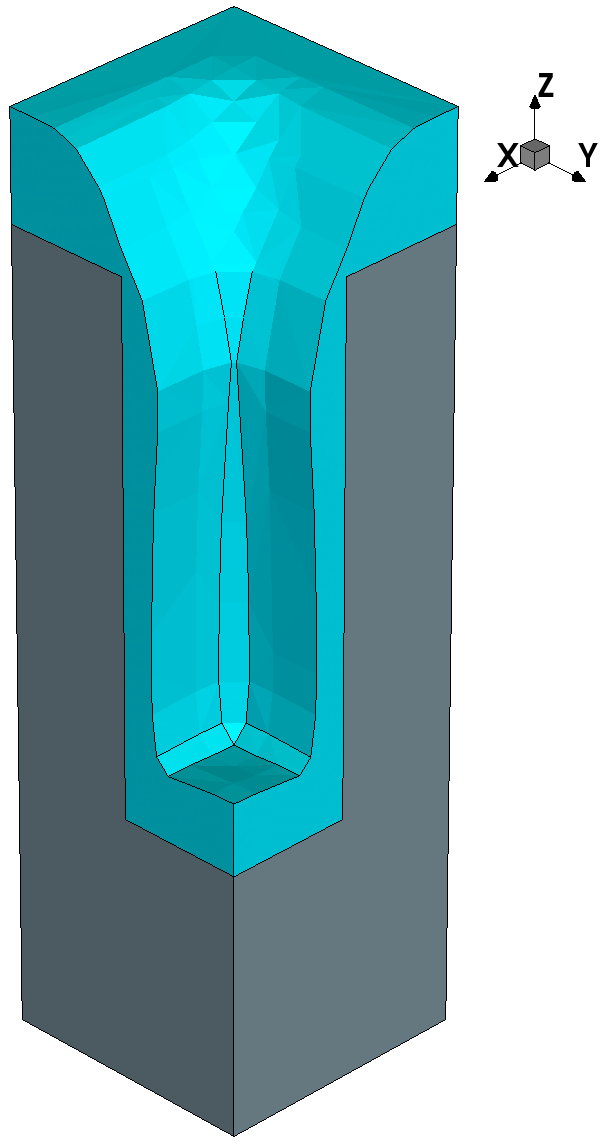
Figure 2. Resulting structure after HDP deposition of oxide on top of silicon substrate. (Click image for full-size view.)
2.5 Integration With Sentaurus Process
To show how to use the functionality of Sentaurus Topography 3D from within Sentaurus Process, the HDP deposition example is replicated here in Sentaurus Process.
The init command replaces the define_structure command:
init tdr= @pwd@/init.tdr
Here, the initial structure is obtained directly by loading a TDR boundary file.
The topo command of Sentaurus Process calls all the related functionality of Sentaurus Topography. For example, the following commands call the Sentaurus Topography 3D define_deposit_machine and deposit commands from Sentaurus Process:
topo define_deposit_machine model= hdp material= Oxide rate= 2 \
	anisotropy= 0.7 exponent= 100 redeposition= 0.1 \
	sputter_rate= 0.95 s1= 5.5 s2= -6 sticking= 0.1

topo deposit spacing= {0.01 0.01 0.015} time= 0.04
Finally, the struct command is used instead of the save command:
struct tdr= n@node@_final.tdr
The complete Sentaurus Process project can be accessed from within Sentaurus Workbench in the directory Applications_Library/GettingStarted/sptopo3d/depo_hdp_sp. Alternatively, you can find the preprocessed script file depo_hdp_sp_fps.cmd in this directory.
To download the preprocessed script file, right-click the following link and choose Save Target As: depo_hdp_sp_fps.cmd.
To execute the file in Sentaurus Process on the command line, type:
> sprocess depo_hdp_sp_fps.cmd
After the command file is executed, the generated TDR file is final.tdr.
Copyright © 2022 Synopsys, Inc. All rights reserved.