
Sentaurus Process
5. Working With Custom Calibration Files
5.1 Overview
5.2 Process-Dependent Settings
5.3 Example: p-Well Implantation
5.4 Example: Implantation With Ge Preamorphization
5.5 Documenting Parameter Changes
Objectives
- To demonstrate how to work efficiently with custom calibration files.
5.1 Overview
The files discussed in this section are part of the Sentaurus Workbench project Custom_calibration. The complete project can be investigated from within Sentaurus Workbench in the directory Applications_Library/GettingStarted/ sprocess/Custom_calibration.
Models can be selected and parameters can be changed at any place in a command file. However, this makes the command file difficult to read and detracts from the process flow itself.
Sentaurus Process offers an elegant way to manage the selection of process step–dependent models and parameters: a calibration file.
A calibration file consolidates all model selections and parameter settings in one location. Using calibration files has several advantages:
- Cleaner command files
- Easy reuse of calibrated models and parameters for different projects
- Easy sharing of calibrated processing steps
- Effective knowledge transfer from experienced to less experienced users
- Buildup of a custom database for calibration results
To load a calibration file at the beginning of a Sentaurus Process command file, use:
source @pwd@/calibration.fps
The recommended way is first to load Advanced Calibration as a starting point and then to load an additional calibration file (see Section 6. Working With Advanced Calibration).
5.2 Process-Dependent Settings
In the example discussed here, the calibration file calibration.fps contains some model and parameter settings.
Click to view the calibration file calibration.fps.
Often, you need to adjust models and parameters for a specific processing step. This can be accomplished by making the relevant selections immediately before the processing step, for example:
pdbSet Silicon Boron IFactor 2.5
implant Boron dose=1e12<cm-2> energy=20<keV> tilt=0 rotation=0
However, Sentaurus Process supports a more elegant method: callback procedures. For example, Sentaurus Process calls the UserImpPreProcess function before and the UserImpPostProcess function after each implantation step. By redefining these user callback procedures in the calibration file, the Sentaurus Process command file can be restricted to contain only generic process flow definitions, and all parameter and model settings can be placed in the calibration file.
A similar concept is implemented in the Advanced Calibration file (see Section 6. Working With Advanced Calibration), where parameters and models are adjusted depending on the implantation conditions, such as species, implantation energy, and dose. This approach is very effective for a global calibration.
In Advanced Calibration, the Sentaurus Process callback procedures after ion implantation are redefined. The user callback procedures are not modified and can be used for additional calibration.
For the calibration of a single project, it is more convenient to adjust models and parameters for a specified processing step. For example, in the command file of Sentaurus Process, introduce the variable ProcessStepID, which identifies the processing step, with:
source @pwd@/calibration.fps
set ProcessStepID "PWell Implantation"
implant Boron dose= 1e12<cm-2> energy= 20<keV> tilt= 0 rotation= 0 info= 2
In the calibration file calibration.fps, write the following redefinition of the preimplantation callback procedure:
proc UserImpPreProcess { Species Energy Dose Tilt Rotation Slice Mode } {
  global  ProcessStepID
  if { [ string match $ProcessStepID "PWell Implantation" ] } {
    ChangeParameter "pdbSet Silicon Boron IFactor 2.5"
  }
This setup has the same effect as the Sentaurus Process code given at the beginning of this section. The variable IFactor is set to 2.5 for the given implantation step and controls the interstitial concentration after the implantation. The number of interstitials is set to be IFactor multiplied by the number of implanted dopant atoms.
In this setup, modified parameters are not reset automatically to their default values. Therefore, any parameter changes remain active for all subsequent processing steps, unless they are explicitly changed again.
5.3 Example: p-Well Implantation
This example illustrates the use of a calibration file for a 1D Sentaurus Process simulation. The example is presented in the form of a Sentaurus Workbench project, which contains two experiments, which are distinguished by the Sentaurus Workbench parameter calibration. In the first experiment, calibration=off. In the second experiment, calibration=on.
The Sentaurus Process command file sprocess_fps.cmd contains the Sentaurus Workbench preprocessor directive:
#if [string compare @calibration@ "on"] == 0
source  @pwd@/calibration.fps
#endif
Click to view the command file sprocess_fps.cmd.
In the calibration=on experiment, the calibration file calibration.fps is read before the Sentaurus Process command file is executed. In the calibration=off experiment, default values are used.
After setting up the grid and defining the substrate, the p-well implantation step is performed (see the command file sprocess_fps.cmd):
set        ProcessStepID "PWell Implantation"
#---------------------------------------------------------------------
deposit material= {Oxide} type= isotropic rate= {1.0} time= 0.01

LogFile "Boron IFactor before implant: [pdbGet Silicon Boron IFactor]"
LogFile "Boron AcInit  before implant: [pdbGetDouble Silicon Boron AcInit]"

implant  Boron dose= 1e12<cm-2> energy= 20<keV> tilt= 0 rotation= 0 info= 2

LogFile "Boron IFactor after implant: [pdbGet Silicon Boron IFactor]"
LogFile "Boron AcInit  after implant: [pdbGetDouble Silicon Boron AcInit]"

SetPlxList { Boron_Implant Int_Implant }
WritePlx   n@node@_PWellimpl.plx   y=0


#---------------------------------------------------------------------
The AcInit parameter is used to determine the value of the active concentration of dopants in crystalline regions, which is used to initialize an annealing step.
The LogFile commands are included only to illustrate the functionality of the callback procedures and can be removed to simplify the structure of the command file.
The calibration file calibration.fps contains the lines:
proc UserImpPreProcess { Species Energy Dose Tilt Rotation Slice Mode } {
  global  ProcessStepID
  if { [ string match $ProcessStepID "PWell Implantation" ] } {
    ChangeParameter "pdbSet Silicon Boron IFactor 2.5"
  }
 proc UserImpPostProcess { Species Name Energy Dose Model IFac VFac CDose } {
  global  ProcessStepID
  if { [ string match $ProcessStepID "PWell Implantation" ] } {
    ChangeParameter "pdbSetDouble Silicon Boron AcInit 5e16"
  }
Open the log file output of Sentaurus Process for the calibration=on experiment to see the callback procedures at work. Look for the lines:
Boron IFactor before implant: 1.0
Boron AcInit  before implant: 5e+18
---------------------------------------------------------------- implant -----
implant info= 2 energy= 20.00<keV> dose= 1.00e+12<cm-2>
tilt= 0.00e+00<degree> rotation= 0.00e+00<degree> Boron
------------------------------------------------------------------------------
<more information on implantation settings>
- - - - - - - - - - - - - - - - - - - - - - - - - - - - - - - - - - - - - - -
Preprocessing implant data

Selecting implant tables for species: Boron
ProcessStepID is "PWell Implantation"
Redefining: pdbSet Silicon Boron IFactor 2.5
<more information on implantation tables>
<...performing the implantation...>Building implantation models

Postprocessing implantation data

Redefining: pdbSetDouble Silicon Boron AcInit 5e16
- - - - - - - - - - - - - - - - - - - - - - - - - - - - - - - - - - - - - - -

 Dose in:   Silicon_1     Oxide_1       Total
              Silicon       Oxide
    Boron  1.9909e+12  1.0337e+10  2.0013e+12
- - - - - - - - - - - - - - - - - - - - - - - - - - - - - - - - - - - - - - -

Boron IFactor after implant: 2.5
Boron AcInit  after implant: 5e+16
------------------------------------------------------------- SetPlxList -----
SetPlxList { Boron_Implant Int_Implant }
------------------------------------------------------------------------------
--------------------------------------------------------------- WritePlx -----
WritePlx n3_PWellimpl.plx y=0
------------------------------------------------------------------------------
The LogFile commands in the Sentaurus Process command file generated the blue text. The LogFile commands in the calibration file calibration.fps generated the red text.
The first set of blue lines shows the Sentaurus Process default values for IFactor and AcInit. Immediately before the implantation is performed, Sentaurus Process calls the UserImpPreProcess callback procedure and changes IFactor according to the requested value for the process step PWell Implantation (see the first and second red lines).
After the implantation is completed, Sentaurus Process calls the UserImpPostProcess callback procedure and changes AcInit according to the requested value for the process step PWell Implantation (see the third red line).
After the implantation step is completed, the changed values for IFactor and AcInit are still active as shown in the last set of blue lines in the log file.
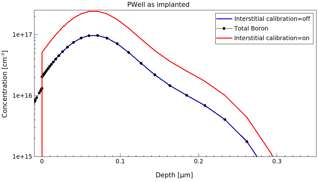
Figure 1. Interstitial concentration immediately after implantation for the calibration=on experiment (red) and calibration=off experiment (blue). Black dots show as-implanted boron profile. (Click image for full-size view.)
For the default IFactor=1, the interstitial profile is identical to the boron profile itself. With the calibrated value of IFactor=2.5, the interstitial profile is 2.5 times larger.
To see the figures shown here within the project, select all Sentaurus Visual nodes and click the Run Selected Visualizer Nodes Together toolbar button.
The AcInit parameter determines the value of the active concentration of dopants in crystalline regions, which is used to initialize an annealing step. To show the influence of this parameter change, a very short (test) anneal step is included in the sprocess_fps.cmd command file:
diffuse   time= 1.0e-12<min>   temp= 600<C>

SetPlxList { BTotal BActive ITotal }
WritePlx   n@node@_PWellrta_init.plx   y= 0
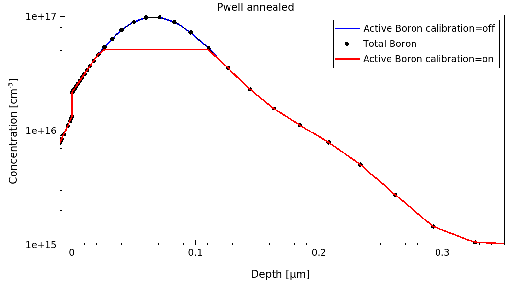
Figure 2. One-dimensional profiles of boron concentration with default value of boron active concentration (calibration=off) and with calibrated value of boron active concentration (calibration=on). (Click image for full-size view.)
The initial activation level is determined as the lower value of the as-implanted doping concentration and the AcInit value. For the default setting of AcInit = 5 x 10¹⁸ (blue), all boron is assumed to be active. After changing AcInit to 5 x 10¹⁶, most of the boron is assumed to be in clusters (red).
5.4 Example: Implantation With Ge Preamorphization
To ensure shallow junctions for the low-doped drain (LDD) implantations, sometimes, an additional implantation step with an electrically inactive dopant (mainly germanium) is performed to amorphize the top silicon layer. This suppresses channeling and avoids deep tails of the as-implanted profiles.
In this example, a high-dose germanium implantation is performed before the boron LDD and the quad arsenic halo implantation, with the following commands:
set       ProcessStepID "PMOS Halo/LDD"
#---------------------------------------------------------------------
implant Germanium dose= 2e14<cm-2> energy= 100<keV> tilt= 0 rotation= 0
implant Boron     dose= 5e14<cm-2> energy=   2<keV> tilt= 0 rotation= 0 \
  info= 2
implant Arsenic  dose= 6e13<cm-2> energy= 60<keV> tilt= 15<degree> rotation= 0 \
  mult.rot= 4  info= 2

SetPlxList { Boron_Implant Arsenic_Implant Damage Int_Implant}
WritePlx   n@node@_LDDimpl.plx   y= 0
Click to view the command file sprocess_fps.cmd.
For this process step, the calibration file calibration.fps contains the following redefinitions:
proc UserImpPreProcess { Species Energy Dose Tilt Rotation Slice Mode } {
  global  ProcessStepID
  if { [ string match $ProcessStepID "PWell Implantation" ] } {
    ChangeParameter "pdbSet Silicon Boron IFactor 2.5"
  }

  if { [ string match $ProcessStepID "PMOS Halo/LDD" ] } {

    switch $Species {
      "Germanium" {
        ChangeParameter "pdbSet Silicon Germanium IFactor 0.2"
      }
      "Boron" {
        ChangeParameter "pdbSet Silicon Boron IFactor 0.1"
        ChangeParameter "implant spec=Boron Silicon ratio=0.9999"
      }
      "Arsenic" {
        ChangeParameter "pdbSet Silicon Arsenic IFactor 0.2"
        ChangeParameter "pdbSet Silicon Arsenic VFactor 0.05"
        ChangeParameter "implant spec=Arsenic  Silicon ratio=0.9999"
      }
    }
  }
}
Besides the IFactor (and for arsenic, also the VFactor) redefinitions, implantation settings for boron and arsenic are modified. The keyword ratio determines the percentage of the total dose that is assigned to the amorphous profile (the rest is assigned to the channeling profile). The setting of ratio=0.9999 almost fully suppresses channeling.
By default, Sentaurus Process takes into account channeling suppression due to the damage generated by previous implantations, in both analytic and Monte Carlo simulations. In this example, this feature has been switched off to show the calibration methodology.
In this callback procedure, a Tcl switch statement makes a specific parameter redefinition for each implanted species (see Section 2.7 Conditional Branching).
These modifications are documented in the n3_fps.out log file:
---------------------------------------------------------------- implant -----
implant info= 2 energy= 2.00<keV> dose= 5.00e+14<cm-2> tilt= 0.00e+00<degree>
        rotation= 0.00e+00<degree> Boron
------------------------------------------------------------------------------
<more information on implantation settings>
- - - - - - - - - - - - - - - - - - - - - - - - - - - - - - - - - - - - - - -
Preprocessing implant data

Selecting implant tables for species: Boron
Redefining: pdbSet Silicon Boron IFactor 0.1
Redefining: implant spec=Boron Silicon ratio=0.9999
Building implant models

---- ---- ---- ---- ---- ---- ---- ---- ---- ---- ---- ---- ---- ---- ---- ---
Material: Silicon
Region:   Silicon_1

Vertical moments
Cap        Rp         Stdev      Gamma      Beta       Ratio      PR
um         um         um
0          0.0094467  0.0087927  -0.40433   9.9194     0.9999     P4
           0.022467   0.022548   -0.96512   4.9372     1e-04      P4
<more range table entries>
The corresponding lines in the log file for the calibration=off experiment read:
Opening table file: /ImpLib/Default/SiliconB_16e13-8e15.tab

Vertical moments
Cap        Rp         Stdev      Gamma      Beta       Ratio      PR
um         um         um
0          0.0094467  0.0087927  -0.40433   9.9194     0.4951     P4
           0.022467   0.022548   -0.96512   4.9372     0.5049     P4
The modifications due to the calibration are highlighted in red and the default values are blue.
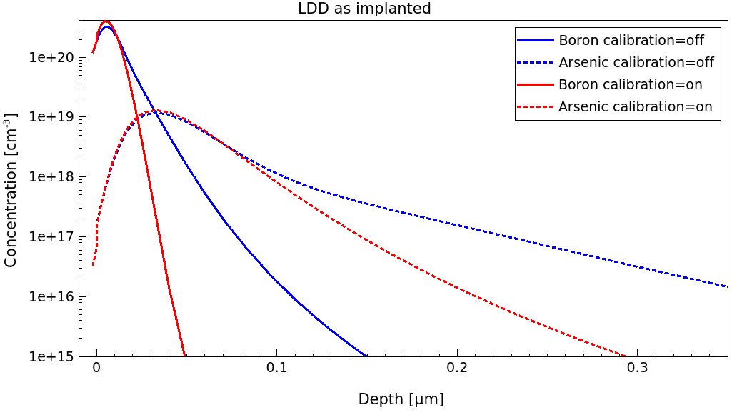
Figure 3. As-implanted boron profiles (solid lines) and arsenic profiles (dashes) with the calibration of the "ratio" parameter to account for preamorphization (red) and with the default implantation tables (blue). (Click image for full-size view.)
After the various implantation steps, the postprocessing callback procedure UserImpPostProcess is called, which for the "PMOS Halo/LDD" step is redefined in the calibration file calibration.fps as:
# Dechanneling after Ge implantation.
#
proc UserImpPreProcess { Species Energy Dose Tilt Rotation Slice Mode } {
  global  ProcessStepID
  if { [ string match $ProcessStepID "PMOS Halo/LDD" ] } {

    switch $Species {
      "Arsenic" {
        ChangeParameter "pdbSet Silicon Arsenic  AcInit  1e17"
        ChangeParameter "pdbSet Silicon Arsenic  AmInit  2e19"
      }
      "Boron" {
        ChangeParameter "pdbSet Silicon Boron    AcInit  1e17"
        ChangeParameter "pdbSet Silicon Boron    AmInit  1e19"
      }
    }
  }
}
In particular, the parameter AmInit limits the (initial) activation level in recrystallized amorphous regions. Here, for example, the boron activation level is limited to 1019 cm-3.
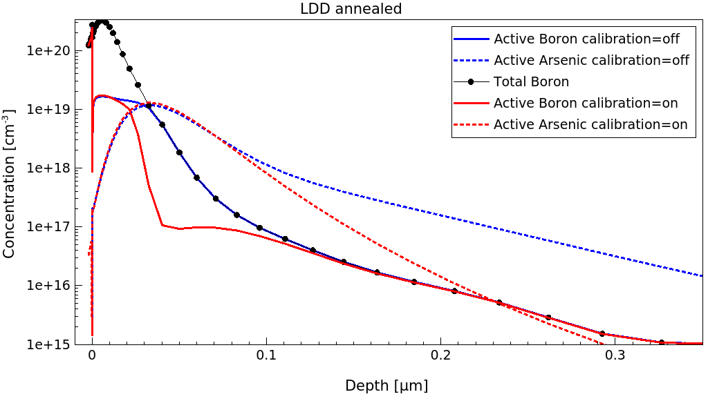
Figure 4. Annealed boron profiles (solid lines) and arsenic profiles (dashes) with calibrated parameters set (red) and default parameters set (blue). (Click image for full-size view.)
Using the default parameters results in excessively deep profiles because preamorphization is neglected. The effect of setting AmInit for boron to 1019 cm–3 can be seen in the highly doped regions.
5.5 Documenting Parameter Changes
In the calibration file calibration.fps, a special procedure generates entries in the log file, which document all the parameter and model changes:
set LastProcessStepID "none"
proc ChangeParameter { CMD } {
  global  ProcessStepID
  global  LastProcessStepID

  if { $LastProcessStepID != $ProcessStepID } {
    LogFile "ProcessStepID is \"$ProcessStepID\""
  }
  LogFile "Redefining: $CMD"
  eval $CMD
  set LastProcessStepID $ProcessStepID
}
The Tcl procedure ChangeParameter writes ProcessStepID for each new process flow step into the log file and writes the parameter and model change commands before executing them.
Copyright © 2022 Synopsys, Inc. All rights reserved.