
Sentaurus Mesh
5. Axis-Aligned Mesh Options
5.1 Mesh Smoothing
5.2 Mesh Delaunization
Objectives
- To introduce the axis-aligned mesh options of Sentaurus Mesh.
5.1 Mesh Smoothing
By default, Sentaurus Mesh applies an automatic mesh-smoothing procedure when constructing a mesh to ensure that the mesh-element aspect ratio (the relative difference between adjacent mesh element edges) is maintained.
You can control mesh-smoothing by changing the parameters in the AxisAligned section of the Sentaurus Mesh command file, including:
AxisAligned {
  smoothing = true | false
  maxAspectRatio = float
  maxNeighborRatio = float
  minEdgeLength = float
  maxAngle = float
  xCuts = floatlist
  yCuts = floatlist
  zCuts = floatlist
  fitInterfaces = true | false
}
where:
- smoothing switches on (true) or off (false) mesh smoothing. If smoothing=true (default), the binary tree uses the maxAspectRatio and maxNeighborRatio parameter values for the mesh step grading.
- maxAspectRatio specifies the maximum-allowed element aspect ratio in the binary tree (default is 1e6).
- maxNeighborRatio specifies the size ratio between adjacent elements (default is 2 in 2D, 4 in 3D).
- minEdgeLength sets the minimum-allowed element edge length produced on the boundary before delaunization (default is 1e-7 μm).
- maxAngle determines the maximum angle produced in the binary tree (default is 90° in two dimensions and 165° in three dimensions).
- fitInterfaces instructs Sentaurus Mesh to calculate the Cuts automatically by first refining along axis-aligned interfaces.
For the rest of the parameters of the AxisAligned section, refer to the Sentaurus™ Mesh User Guide.
The Applications_Library/GettingStarted/snmesh/Smoothing Sentaurus Workbench project demonstrates how mesh-smoothing controls work for the above examples. To work with this project, copy it to a local directory within your Sentaurus Workbench working directory.
The Sentaurus Mesh tool instances labeled NoSmooth and Smooth demonstrate the consequence of the smoothing deactivation for the previously shown device structure (see Figure 1).
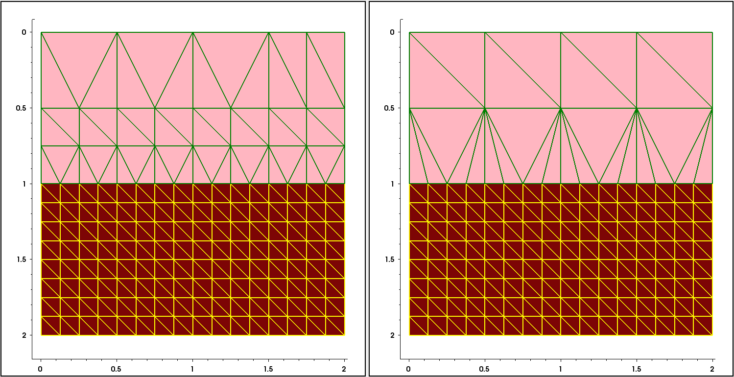
Figure 1. (Left) With smoothing=true and (right) with smoothing=false. (Click image for full-size view.)
Using smoothing=false, the mesh-step propagation from the material with the smaller step (oxide) towards the material with the higher step definition (silicon) is suppressed.
The next example illustrates the influence of the maxNeighborRatio parameter value on the mesh step smoothing for the previously shown example, with one order of magnitude step difference inside and outside the rectangular area, located in the middle of the device (see Figure 2).
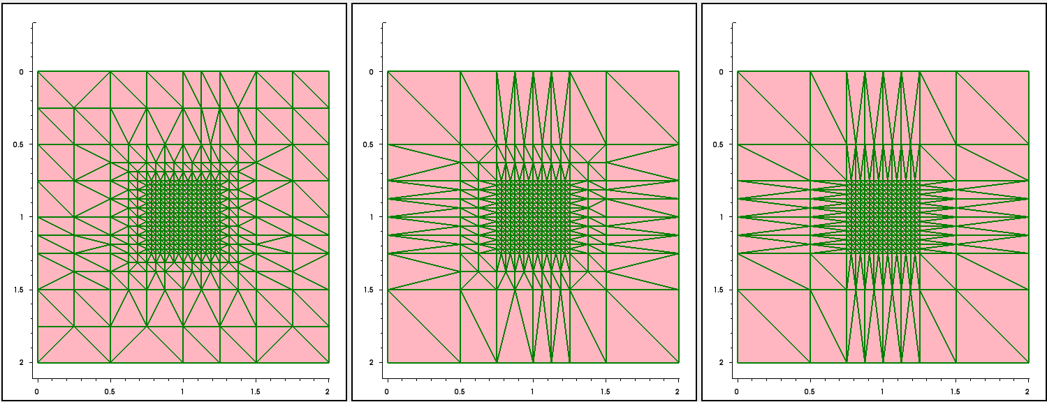
Figure 2. (Left) With maxNeighborRatio=2, (middle) maxNeighborRatio=4, and (right) maxNeighborRatio=8. (Click image for full-size view.)
The Sentaurus Mesh tool instance labeled NB_Ratio demonstrates the consequence of maxNeighborRatio control settings. Together with the smoothing control examples above, it is contained in the Applications_Library/GettingStarted/snmesh/Smoothing Sentaurus Workbench project.
5.2 Mesh Delaunization
Mesh delaunization is a mandatory meshing step. It produces final grids suitable for the box discretization method, which is used in Sentaurus Process and Sentaurus Device. Delaunization is the most critical part in the case of 3D meshing, which requires some occasional compromises to produce a suitable mesh in terms of quality and size (node count). For 2D meshing, fully Delaunay grids are usually produced.
The delaunization step focuses on several targets. The major ones are:
- Each mesh element must meet the Delaunay triangulation criterion. This ensures that convergence is maintained on the simulator side.
- Slivers (elements with zero volume) must be eliminated.
- You must control the average node connectivity.
- During delaunization, the aspect ratio of neighbor elements is maintained.
The delaunization step controls are in the Delaunizer section of the Sentaurus Mesh command file:
Delaunizer {
  coplanarityAngle = float
  coplanarityDistance = float
  delaunayTolerance = float
  edgeProximity = float
  faceProximity = float
  maxAngle = float
  maxConnectivity = float
  maxNeighborRatio = float
  maxPoints = integer
  maxSolidAngle = float
  maxTetQuality = float
  minAngle = float
  minEdgeLength = float
  sliverAngle = float
  sliverDistance = float
  sliverRemovalAlgorithm = integer
  storeDelaunayWeight = true | false
  type = boxmethod | conforming | constrained
}
where:
- The parameter type specifies which type of Delaunay mesh must be produced:
- boxmethod (default): Imposes the strictest conditions on the boundaries, requiring an almost ideal Delaunay mesh to be produced.
- conforming: Equivalent to the standard Delaunay condition, where more relaxed conditions are used for the boundaries of the element.
- constrained: Produces the least refinement of all these options. The meshes are often unsuitable for device simulation.
Sentaurus Device simulations require meshes created using type=boxmethod. For Sentaurus Process simulations, creating a slightly non-Delaunay mesh can drastically reduce the node count without sacrificing simulator accuracy. - The parameter delaunayTolerance uses a floating-point number (it must be
between 0 and 1) to specify how close the ridges and boundary faces conform to the
Delaunay criterion. A value of 0 implies a very strict Delaunay criterion. A value of 1 is
equivalent to the construction of a constrained Delaunay triangulation (CDT). The
delaunayTolerance can be defined materialwise or regionwise. For example, the following
specification activates the CDT in oxide material only, while everywhere else the boxmethod
Delaunay triangulation is used:
Delaunizer {... delaunayTolerance=0 interior material "Oxide" {delaunayTolerance=1} } - The parameter maxPoints sets a limit on the maximum number of vertices that the delaunizer generates (default is 100000). Be careful because, when meshing a large 3D device, this value can be exceeded easily. In this case, the delaunizer will stop a triangulation and the final mesh might be non-Delaunay.
- The parameters maxAngle and minAngle specify the maximum and minimum angles allowed, respectively, in mesh elements (2D only).
- The parameter minEdgeLength sets the threshold for the minimum-allowed element edge length (default is 1e-9 μm).
- The parameter maxNeighborRatio specifies the maximum-allowed ratio between the circumscribed spheres of neighbor elements. It can be used in combination with the maxNeighborRatio option of the AxisAligned section for better mesh grading (default is 2 in two dimensions, 4 in three dimensions).
For the rest of the parameters of the Delaunizer section, refer to the Sentaurus™ Mesh User Guide.
Figure 3 shows the results of varying the value of minAngle for the previously shown example.
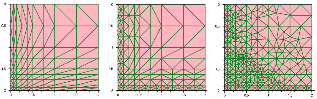
Figure 3. Mesh with minAngle equal to (left) 5°, (middle) 15°, and (right) 30°. (Click image for full-size view.)
Copyright © 2022 Synopsys, Inc. All rights reserved.