
Sentaurus Mesh
3. Meshing at Interfaces
3.1 Overview
3.2 Interface Refinement
3.3 Offsetting
Objectives
- To describe interface mesh refinement in Sentaurus Mesh.
3.1 Overview
In most semiconductor devices, interfaces between two materials play a significant role. Therefore, a finer mesh is typically required at critical interfaces. Sentaurus Mesh provides the following mechanisms to specify an interface mesh:
- Interface refinement provides an easy way to specify a finer mesh near the interface for the axis-aligned mesh generator.
- Offsetting allows you to build mesh lines that follow the contours of the interface.
In general, interface refinement is useful when the interface is generally straight and along one of the x-axis, y-axis, or z-axis directions. In cases where the interface is highly curved or not axis-aligned, offsetting is recommended.
3.2 Interface Refinement
The Sentaurus Mesh command files featured in this section are all contained in the Sentaurus Workbench project Applications_Library/GettingStarted/snmesh/RefineInterface. To work with the project, copy it to a local directory within your Sentaurus Workbench working directory.
A frequently useful feature in Sentaurus Mesh is interface mesh refinement, which allows you to gradually resolve material interfaces in an isotropic manner.
The interface mesh refinement controls are embedded into a refinement region specification in the Definitions section:
Refinement "reference name" {
  MaxElementSize = (<xmax> <ymax> <zmax>)
  MinElementSize = (<xmin> <ymin> <zmin>)
  RefineFunction = MaxLengthInterface(Interface("<Material1>","<Material2>"),
                   Value = value, Factor = value [DoubleSide] [UseRegionNames])
}
where:
- Interface("<Material1>","<Material2>") indicates the materials whose interface must be refined.
- Value specifies the value of the initial mesh step at the interface.
- Factor controls the grading of the element sizes across the interface.
- DoubleSide (optional) initiates the mesh refinement on both sides of the interface. By default, the interface is refined inside <Material1> only.
- UseRegionNames (optional) interprets an interface as a regionwise specification.
Multiple RefineFunction definitions are allowed inside a single Refinement statement. Instead of the full MaxLengthInterface name, you can use MaxLenInt, for example:
Refinement "reference name" {
  MaxElementSize = (<xmax> <ymax> <zmax>)
  MinElementSize = (<xmin> <ymin> <zmin>)
  RefineFunction = MaxLenInt(Interface("Material1","Material2"),
                   Value = value, Factor = value)
}
In the RefineInterface project, the Sentaurus Mesh tool instance labeled IntRefA demonstrates the use of the interface refinement option in Sentaurus Mesh, where the interface refinement is applied to both sides of the silicon–SiO2 and polysilicon–SiO2 material interfaces:
Definitions {
  Refinement "global" {
    MaxElementSize = (1 1 1)
    MinElementSize = (0.01 0.01 0.01)
    RefineFunction = MaxLenInt(Interface("Silicon","SiO2"),
             value=0.01, factor=2, DoubleSide)
    RefineFunction = MaxLenInt(Interface("PolySi","All"),
             value=0.01, factor=2, DoubleSide)
  }
}
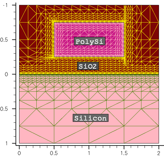
Figure 1. Interface mesh refinement. (Click image for full-size view.)
Click to view the command file IntRefA_msh.cmd.
The interface mesh refinement method works very well for axis-aligned or slightly nonaxis-aligned geometries. However, for strongly curved or nonaxis-aligned device geometries, the interface mesh refinement can produce many mesh points when refining a nonplanar geometry, due to the specifics of the binary tree–based space decomposition, as shown in Figure 2. In general, it is not recommended to use interface refinement on such geometries. Use offsetting instead.
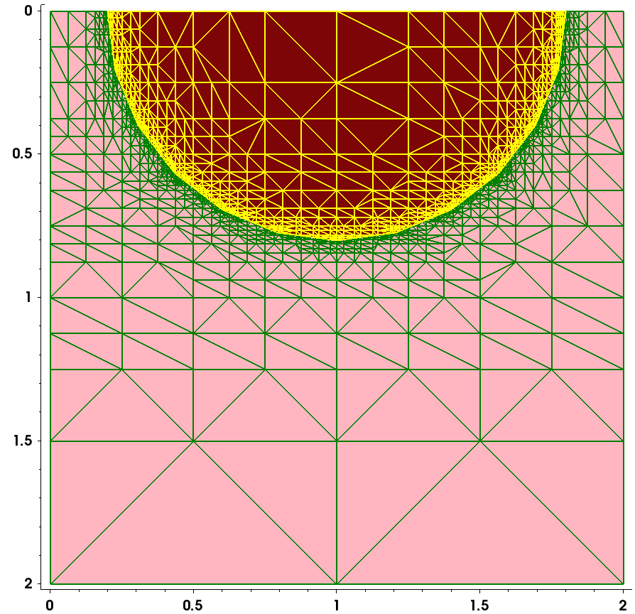
Figure 2. Interface mesh refinement applied to nonaxis-aligned device geometry can produce a huge number of mesh points due to the specifications of the recursive binary-tree decomposition algorithm. (Click image for full-size view.)
In the RefineInterface project, the Sentaurus Mesh tool instance labeled IntRefB demonstrates the behavior of interface mesh refinement applied to a nonaxis-aligned device geometry.
Click to view the command file IntRefB_msh.cmd.
3.3 Offsetting
The possibility to generate boundary-conforming grids, using a combination of binary volume decomposition and offsetting algorithms, is implemented in Sentaurus Mesh.
You activate the offsetting algorithm by specifying the EnableOffset or EnableSections option in the IOControls section of the command file. Without one of these options, the Offsetting section is ignored and boundary-conforming layers are not produced.
The controls for offsetting are specified in the Offsetting section of the command file:
Offsetting {
  noffset {
    hlocal = float
    factor = float
    maxlevel = integer
  }

  noffset material "<material_1>" "<material_2>" {
    factor = float
    hlocal = float
    window = [(float float float) (float float float)]
  }

  noffset material "<material_name>" {
    maxlevel = integer
  }
}
Both materialwise and regionwise specifications are supported.
The offsetting algorithm uses a combination of simple offsetting and level-set methods to generate mesh layers conformal with the material interface.
Offsetting can be confined to a given window using a window specification. This often helps to maintain the best mesh quality for complex device structures. Note that a window controls only the starting position of layering and, therefore, layers can potentially grow outside of the window. Multiple window specifications within the same interface section are supported, but they must all use a common hlocal and factor.
Figure 3 illustrates the most important offsetting parameters mentioned.
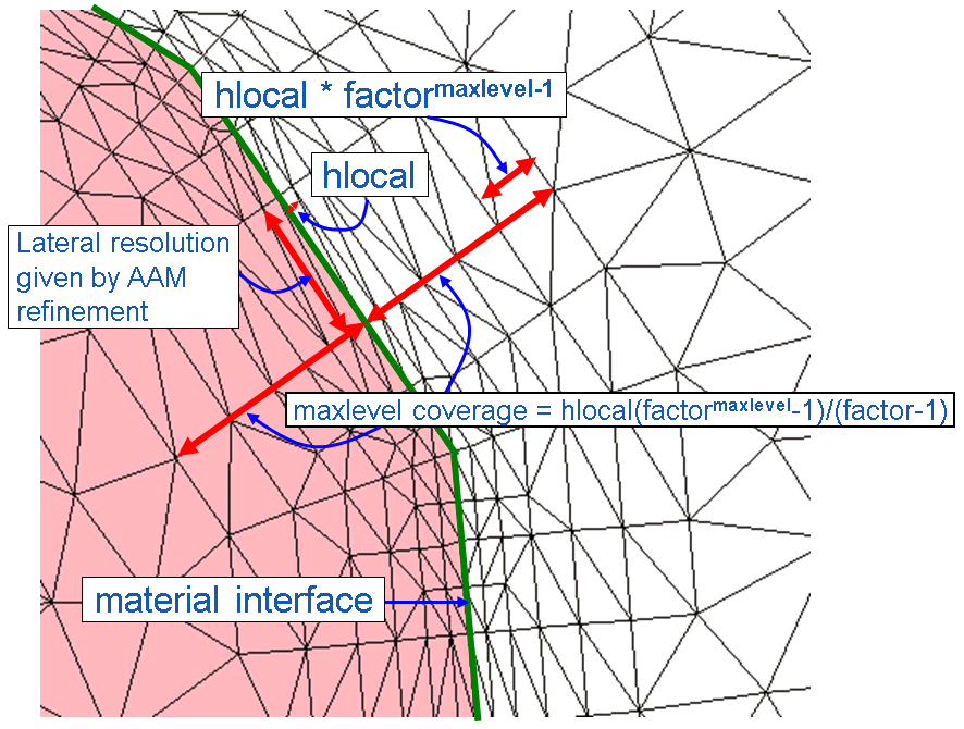
Figure 3. Main parameters related to offset layering at interfaces. At the material interface, the lateral mesh resolution is given by the axis-aligned mesh (AAM) refinement specifications. (Click image for full-size view.)
To illustrate how to use offsetting to generate a boundary-conforming anisotropic mesh layer, you will apply it to the same device structure, as shown in Figure 2. The maxlevel=6 specification has been applied to both the Silicon and Oxide materials, thereby creating six boundary-conforming mesh layers on both sides of the silicon–oxide interface. The layering starts with a layer thickness, specified by the hlocal value in the corresponding noffset material section. This setting applies to the first of two materials, which appear in each particular specification:
Offsetting {

  noffset material "Silicon" {
    maxlevel=6
  }

  noffset material "Oxide" {
    maxlevel=6
  }

  noffset material "Silicon" "Oxide" {
    hlocal=0.01
    factor=1.5
  }

  noffset material "Oxide" "Silicon" {
    hlocal=0.015
    factor=1.6
  }
}
Figure 4 shows the resulting boundary-conforming mesh.
Click to view the command file IntRefC_msh.cmd.
It is not recommended to use the same hlocal on both sides of an interface because this can create poor-quality mesh elements.
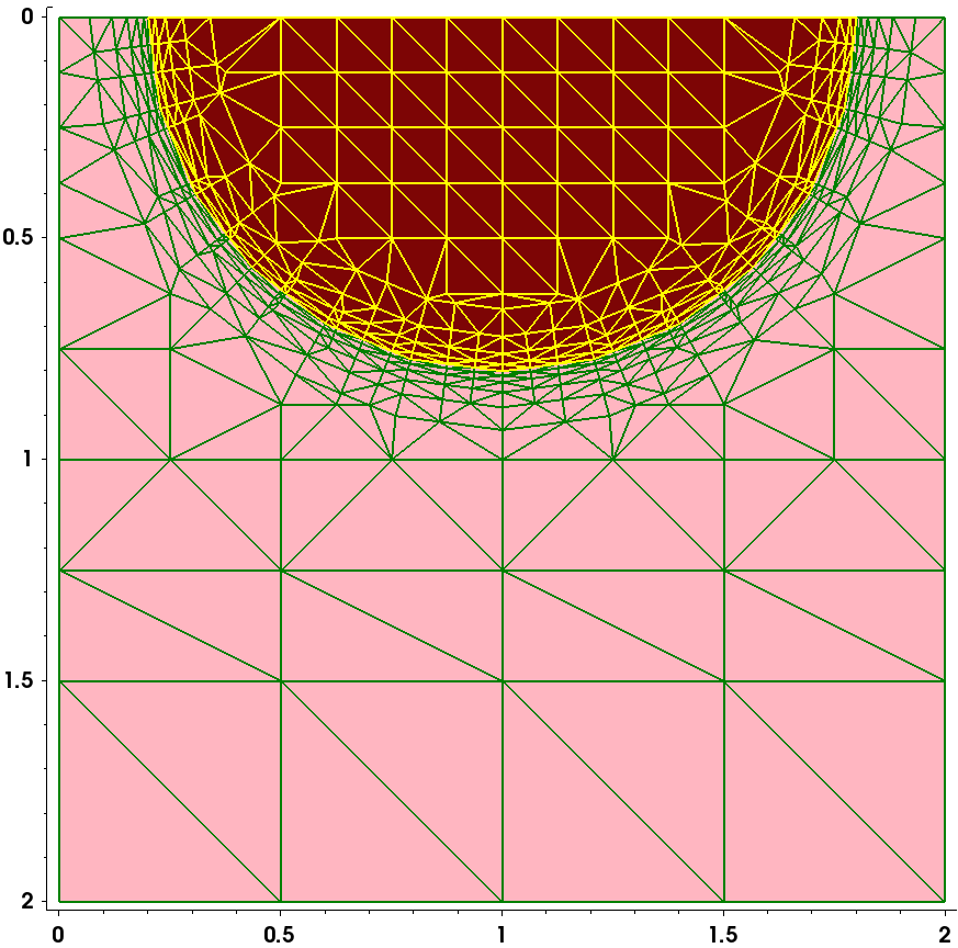
Figure 4. Boundary-conforming interface refinement applied to nonaxis-aligned device geometry by applying offsetting specifications at the silicon–oxide interface by Sentaurus Mesh. (Click image for full-size view.)
The Sentaurus Mesh tool instance labeled IntRefC, contained in the Sentaurus Workbench project Applications_Library/GettingStarted/snmesh/RefineInterface, demonstrates the behavior of interface mesh refinement applied to nonaxis-aligned device geometry. To work with the project, copy it to a local directory within your Sentaurus Workbench directory.
Copyright © 2022 Synopsys, Inc. All rights reserved.