 main menu
| module menu
| << previous section
| next section >>
main menu
| module menu
| << previous section
| next section >>
Sentaurus Device
18. Special Focus: Simulating Ferroelectric Devices
18.1 Overview
18.2 Example: Ferroelectric Hysteresis
18.3 Relevant Examples
Objectives
- To demonstrate the use of ferroelectric models implemented in Sentaurus Device.
18.1 Overview
Ferroelectric materials, such as PbZrxTi1–xO3 (PZT), SrBi2Ta2O9 (SBT), and (Bi,La)4Ti3O12 (BLT), and doped hafnium oxide, are characterized by spontaneous dielectric polarization even when the applied electric field is zero. Polarization in these materials depends nonlinearly on the electric field. The polarization at a given time depends on the electric field at that time and the electric field at previous times. The history dependence leads to the well-known phenomenon of hysteresis.
Different ferroelectric models are available in Sentaurus Device, which cover the full range of ferroelectric device simulation in increasing order of complexity:
- Analytic ferroelectric model (Preisach-based model)
- Directional ferroelectric model (default), which solves the Ginzburg–Landau–Khalatnikov (GLK) equation assuming a single polarization direction
- Advanced edge-based ferroelectric model (Solver II), which uses the full formulation of the GLK equation by assuming the divergence-free polarization constraint
The Preisach-based model, being an analytic model, is simple and numerically efficient compared to the other approaches. The next section explores the Preisach-based model using a ferroelectric capacitor example.
18.2 Example: Ferroelectric Hysteresis
Sentaurus Device implements a Preisach-based model for ferroelectrics that features minor loop nesting and memory wipeout features. This example explores these features.
The complete project can be investigated from within Sentaurus Workbench in the directory Applications_Library/GettingStarted/sdevice/Ferroelectric/Hysteresis.
18.2.1 Project Organization
The simulations are organized in a Sentaurus Workbench project (see Figure 1). The tool flow starts with Sentaurus Structure Editor, which generates the ferroelectric capacitor. The Sentaurus Device tool instances sat_loop, depol, and mem_wipeout simulate the saturation hysteresis loop, the depolarization, and the memory wipeout characteristics of the ferroelectric capacitor. The Sentaurus Visual tool instances next to the Sentaurus Device tools plot the respective characteristics.
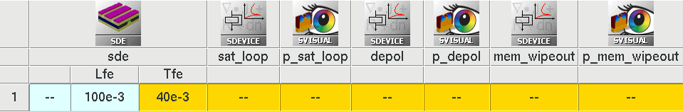
Figure 1. Organization of the project in Sentaurus Workbench. (Click image for full-size view.)
18.2.2 Preisach-Based Model
The basic concept of the Preisach-based approach is to model the material through a cluster of independent dipoles, which can switch between two opposing states. Each dipole has a rectangular hysteresis loop, and superposition of such simple hysteresis units gives the net hysteresis loop. The following parameters that define the hysteresis loop must be extracted from the experimental data for use in the Preisach-based model:
- Saturation polarization, \(P_{\text"s"}\)
- Coercive field, \(F_{\text"c"}\)
- Remanent polarization, \(P_{\text"r"}\)
Figure 2 shows the typical hysteresis plot noting these parameters.
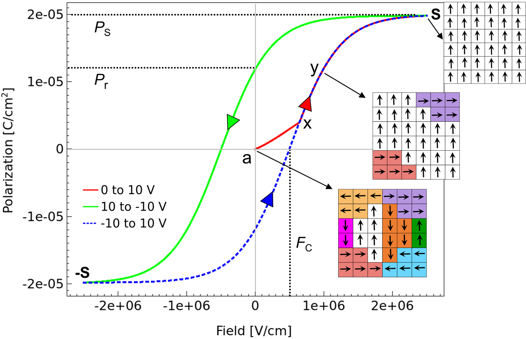
Figure 2. Polarization versus electric field characteristic of the ferroelectric capacitor. The points on the polarization curve are reached in the sequence a, x, y, s, -s, x, y, s. The path represented by points -s, x, y, s, -s forms the saturation loop. (Click image for full-size view.)
Sentaurus Device computes the auxiliary polarization \(P_{\text"aux"}\) as an algebraic function of the auxiliary field \(F_{\text"aux"}\) and is given by:
\( P_{\text"aux"} = c . P_\text"s" . \text"tanh"( w . (F_{\text"aux"} ± F_\text"c" ) ) + P_{\text"off"} \)
where \( w = 1 / {2 F_{\text"c"}} \text"ln" {P_\text"s"+P_\text"r"}/{P_\text"s"-P_\text"r"} \).
The parameters \(P_{\text"off"}\) and c result from the polarization history of the material. The model is activated by specifying the keyword Polarization in the Physics section of the command file:
Physics (Material= "HfO2") {
   Polarization
}
To obtain a plot of the polarization field, Polarization/Vector is specified in the Plot section of the command file:
Plot {
   Polarization/Vector
}
As previously noted, Sentaurus Device characterizes the static properties of a ferroelectric material by three parameters: the remanent polarization (P_r), the saturation polarization (P_s), and the coercive field (F_c). The transient response of the ferroelectric material is characterized by the relaxation times (tau_E, tau_P) and by a nonlinear coupling constant (kn). The following parameter values are specified for the ferroelectric material in the parameter file:
Material = "HfO2" {
   Polarization
   { * P_r, P_s, and Fc for ferroelectric for x,y,z directions
     P_r = (1.2e-5, 1.2e-5, 0)
     P_s = (2e-5, 2e-5, 0)
     F_c = (5e+5, 5e+5, 0)
   }
}
18.2.3 Discussion
The structure used for the simulation is a simple capacitor with two electrodes: top and bottom. Figure 2 shows the simulated hysteresis plot of the ferroelectric capacitor. The points on the polarization curve are reached in the sequence a, x, y, s, -s, x, y, s. An important property of ferroelectric hysteresis is the well-defined saturation loop represented by the sequence -s, x, y, s, -s.
Ferroelectric materials are characterized by dielectric polarization owing to preexisting dipoles in these materials. A group of dipoles having parallel orientation forms a domain. In the inset of Figure 2, each arrow represents a dipole and a unique color is used to represent a domain. At zero electric field, the orientation is such that the net dipole moment is zero and so the polarization is zero (point a in Figure 2) in the absence of an electric field.
With an increasing electric field, more domains align with the electric field, thereby increasing the net polarization (point y). As the field is increased to point s, the net polarization saturates. The end points of the saturation loop are denoted by s and -s. Irrespective of the previous history of the ferroelectric capacitor, polarization points must lie on or within the saturation loop.
Figure 3 shows the electrostatic potential field and polarization vector plots when saving the ferroelectric capacitor states at the saturation end points s and -s, as noted in Figure 2.
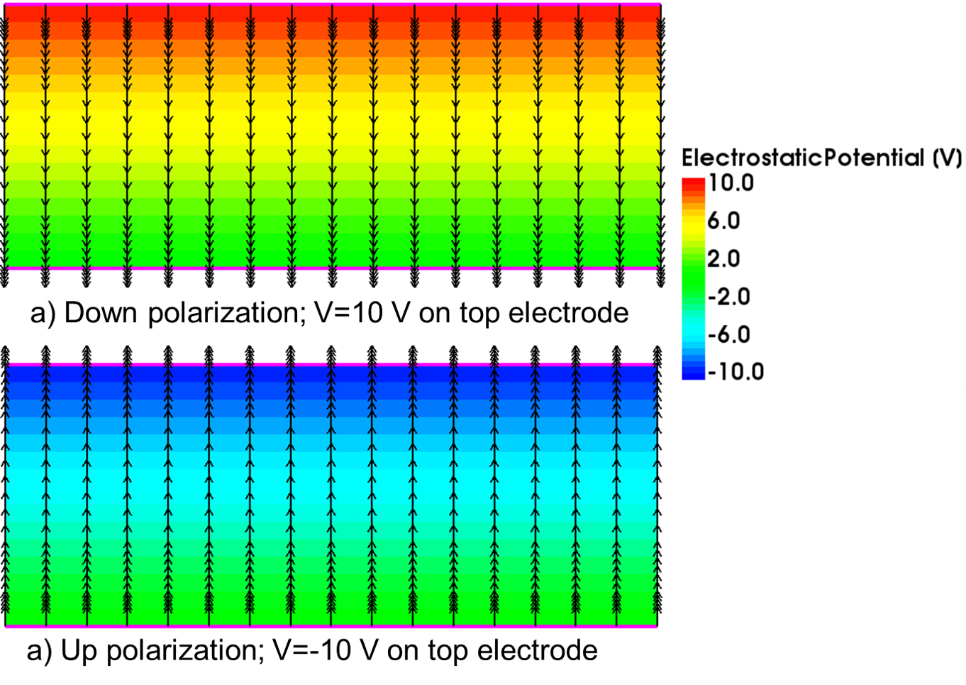
Figure 3. Electrostatic potential field and polarization vector plots: (a) down polarization for positive voltage applied to top electrode and (b) up polarization for negative voltage applied to top electrode. (Click image for full-size view.)
The Preisach-based model allows the simulation of the effect of depolarization (almost zero net polarization at zero applied field) as shown in Figure 4. To simulate this, a triangularly shaped voltage with constantly decreasing amplitude (see inset of Figure 4) is applied to the top electrode of the ferroelectric capacitor. Sentaurus Device records turning points (points where the polarization curve changes direction) as they are encountered during a simulation. Some turning points are noted in Figure 4. The memory always contains s as the oldest turning point and -s as the second-oldest turning point.
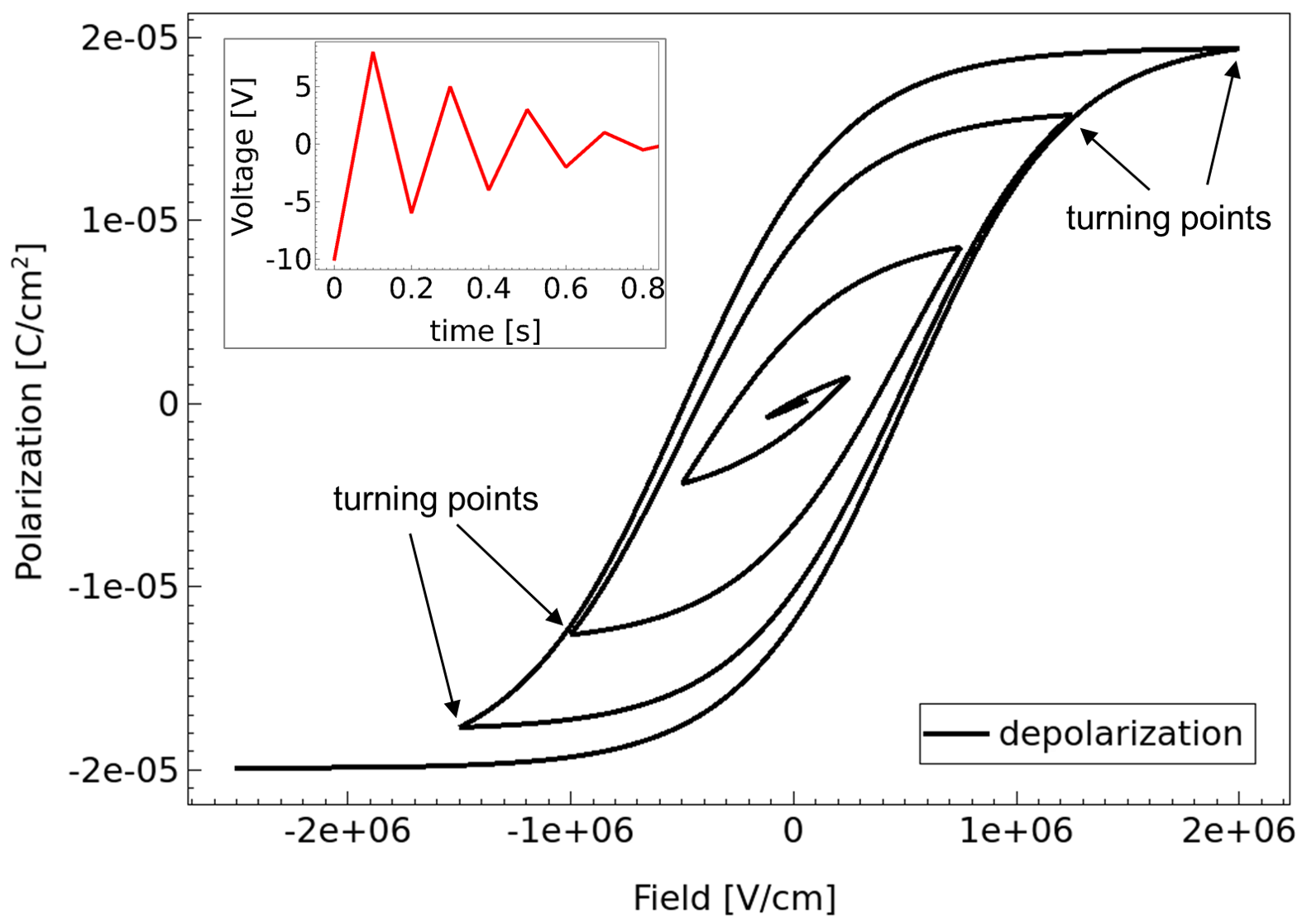
Figure 4. Polarization versus electric field characteristic illustrating depolarization hysteresis loop. Inset shows the applied voltage. (Click image for full-size view.)
Figure 5 illustrates the simulation of memory wipeout, another interesting feature of ferroelectric materials. This effect is seen when the amplitude of the voltage or electric field is increased again after one or more depolarization cycles. The inset of Figure 5 shows the applied voltage. The points on the polarization curve are reached in the sequence a, b, c, b, d. The sequence b, c, b forms a subcycle or minor loop.
Although Preisach-based hysteresis shows history dependence, not all of its prior history needs to be recorded. For example, as the saturation loop is well defined, if a large voltage is applied across the ferroelectric capacitor so that its polarization point is on the saturation curve, then its behavior in the future no longer depends on its past history. This implies that only the alternating series of dominant input voltage extrema are important. After the polarization sequence a, b, c, b, the memory is erased at b as the next polarization point d does not depend on the previous history.
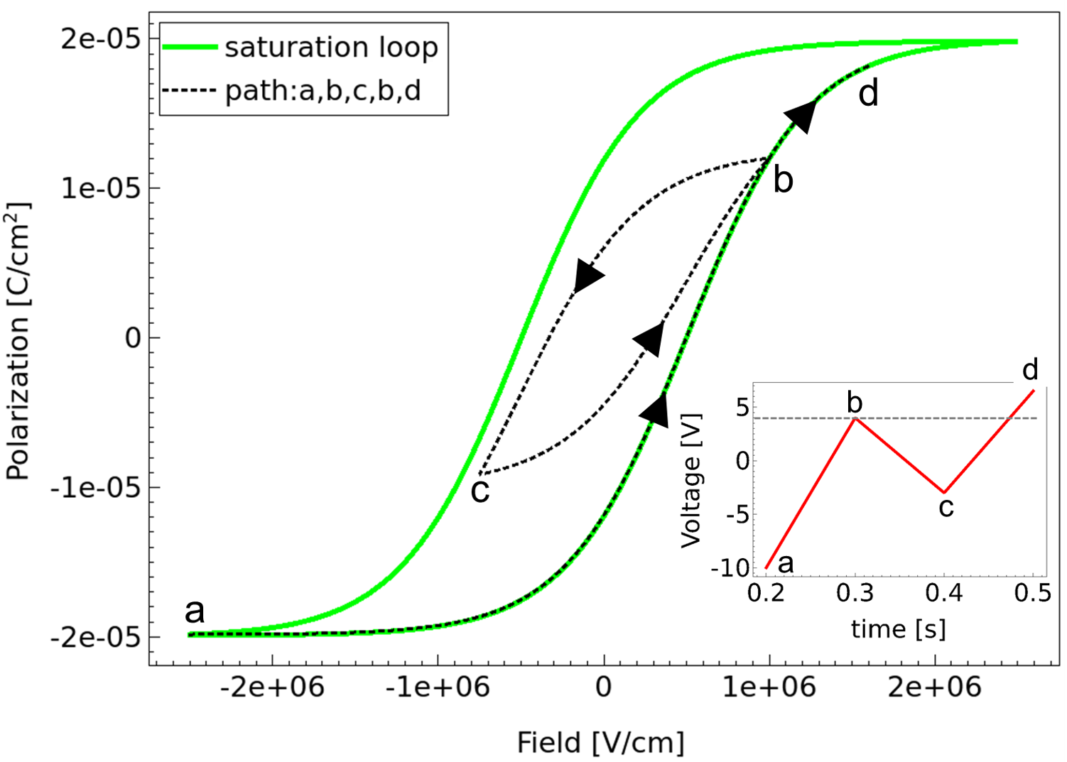
Figure 5. Polarization versus electric field characteristic illustrating memory wipeout; the saturation loop is included for reference. Inset shows the applied voltage. (Click image for full-size view.)
18.3 Relevant Examples
- Ex. 1
- Simulation of Content-Addressable Memory Based on Ferroelectric FET, available from Applications_Library/Memory/FeFET_CAM.
- Ex. 2
- 1T_FeRAM, available from Sentaurus Device Wizard.
- Ex. 3
- Ferroelectric_Capacitor, available from Sentaurus Device Wizard.
- Ex. 4
- Negative_Capacitance_FET, available from Sentaurus Device Wizard.
main menu | module menu | << previous section | next section >>
Copyright © 2022 Synopsys, Inc. All rights reserved.